Projet: remplacer les Quartz des softrock lite II par un générateur à base de SI5351
Afin d’aligner correctement un softrock lite II sur 2220m ou 630m sur la frequence wspr, il est plus simple d’utiliser une clock controlable.
Quoi de plus simple avec un Attiny85 et un SI5351.
1.La platine
Fichier kicad ici: platine_vfo_frequence fixe
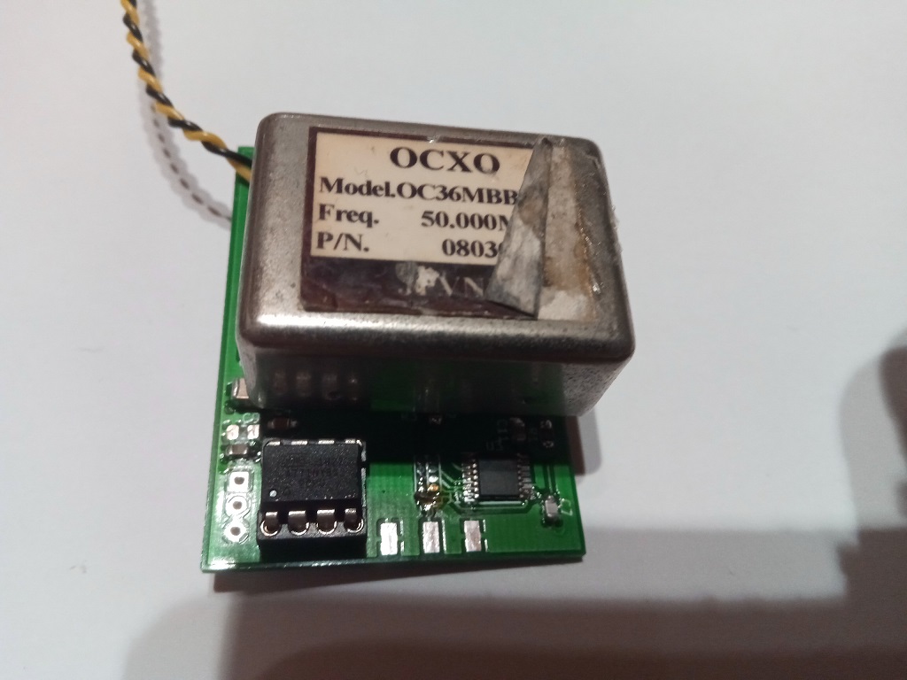
Je pense qu’avec votre expérience il sera facile de reproduire quelque chose avec un module existant adafruit ou autre en connectant ceci avec un Attiny85.
Voici la mienne:
2.Le programme
Attention testé jusqu’à version micronucleus 1.11 .
|
1 2 3 4 5 6 7 8 9 10 11 12 13 14 15 16 17 18 19 20 21 22 23 24 25 26 27 28 29 30 31 32 33 34 35 36 37 38 39 40 41 42 43 44 45 46 47 48 49 50 51 52 53 54 55 56 57 58 59 60 61 62 63 64 65 66 67 68 69 70 71 72 73 74 75 76 77 78 79 80 81 82 83 84 85 86 87 88 89 90 91 92 93 94 95 96 97 98 99 100 101 102 103 |
#include <Wire.h> #define SI5351_i2c_bus_addr 0x60 const byte SI5351_Reg_Store_init[][2] = { //pas en progmem /*{0, 0x00},*/ {1, 0x00}, {2, 0x18}, {3, 0x00}, /*{4, 0x00}, {5, 0x00}, {6, 0x00}, {7, 0x00}, {8, 0x00},*/ {9, 0x00}, /*{10, 0x00}, {11, 0x00}, {12, 0x00}, {13, 0x00}, {14, 0x00},*/ {15, 0x00}, {16, 0x6F}, {17, 0x80}, {18, 0x4F}, {19, 0x80}, {20, 0x83}, {21, 0x80}, {22, 0x80}, {23, 0x80}, {24, 0x00}, {25, 0x00}, {26, 0x0C}, {27, 0x35}, {28, 0x00}, {29, 0x0A}, {30, 0xDC}, {31, 0x00}, {32, 0x02}, {33, 0x74}, {34, 0x0C}, {35, 0x35}, {36, 0x00}, {37, 0x0C}, {38, 0x09}, {39, 0x00}, {40, 0x03}, {41, 0xA3}, {42, 0x00}, {43, 0x01}, {44, 0x00}, {45, 0xB7}, {46, 0x00}, {47, 0x00}, {48, 0x00}, {49, 0x00}, {50, 0x00}, {51, 0x00}, {52, 0x00}, {53, 0x00}, {54, 0x00}, {55, 0x00}, {56, 0x00}, {57, 0x00}, {58, 0x00}, {59, 0x01}, {60, 0x02}, {61, 0x4D}, {62, 0x00}, {63, 0x00}, {64, 0x00}, {65, 0x00}, {66, 0x00}, {67, 0x00}, {68, 0x00}, {69, 0x00}, {70, 0x00}, {71, 0x00}, {72, 0x00}, {73, 0x00}, {74, 0x00}, {75, 0x00}, {76, 0x00}, {77, 0x00}, {78, 0x00}, {79, 0x00}, {80, 0x00}, {81, 0x00}, {82, 0x00}, {83, 0x00}, {84, 0x00}, {85, 0x00}, {86, 0x00}, {87, 0x00}, {88, 0x00}, {89, 0x00}, {90, 0x00}, {91, 0x00}, {92, 0x00}, /*{93, 0x00}, {94, 0x00}, {95, 0x00}, {96, 0x00}, {97, 0x00}, {98, 0x00}, {99, 0x00}, {100, 0x00}, {101, 0x00}, {102, 0x00}, {103, 0x00}, {104, 0x00}, {105, 0x00}, {106, 0x00}, {107, 0x00}, {108, 0x00}, {109, 0x00}, {110, 0x00}, {111, 0x00}, {112, 0x00}, {113, 0x00}, {114, 0x00}, {115, 0x00}, {116, 0x00}, {117, 0x00}, {118, 0x00}, {119, 0x00}, {120, 0x00}, {121, 0x00}, {122, 0x00}, {123, 0x00}, {124, 0x00}, {125, 0x00}, {126, 0x00}, {127, 0x00}, {128, 0x00}, {129, 0x00}, {130, 0x00}, {131, 0x00}, {132, 0x00}, {133, 0x00}, {134, 0x00}, {135, 0x00}, {136, 0x00}, {137, 0x00}, {138, 0x00}, {139, 0x00}, {140, 0x00}, {141, 0x00}, {142, 0x00}, {143, 0x00}, {144, 0x00}, {145, 0x00}, {146, 0x00}, {147, 0x00}, {148, 0x00},*/ {149, 0x00}, {150, 0x00}, {151, 0x00}, {152, 0x00}, {153, 0x00}, {154, 0x00}, {155, 0x00}, {156, 0x00}, {157, 0x00}, {158, 0x00}, {159, 0x00}, {160, 0x00}, {161, 0x00}, {162, 0x00}, {163, 0x00}, {164, 0x00}, {165, 0x00}, {166, 0x00}, {167, 0x00}, {168, 0x00}, {169, 0x00}, {170, 0x00}, /*{171, 0x00}, {172, 0x00}, {173, 0x00}, {174, 0x00}, {175, 0x00}, {176, 0x00}, {177, 0x00}, {178, 0x00}, {179, 0x00}, {180, 0x00}, {181, 0x30}, {182, 0x00},*/ {183, 0xD2}/*, {184, 0x60}, {185, 0x60}, {186, 0x00}, {187, 0xC0}, {188, 0x00}, {189, 0x00}, {190, 0x00}, {191, 0x00}, {192, 0x00}, {193, 0x00}, {194, 0x00}, {195, 0x00}, {196, 0x00}, {197, 0x00}, {198, 0x00}, {199, 0x00}, {200, 0x00}, {201, 0x00}, {202, 0x00}, {203, 0x00}, {204, 0x00}, {205, 0x00}, {206, 0x00}, {207, 0x00}, {208, 0x00}, {209, 0x00}, {210, 0x00}, {211, 0x00}, {212, 0x00}, {213, 0x00}, {214, 0x00}, {215, 0x00}, {216, 0x00}, {217, 0x00}, {218, 0x00}, {219, 0x00}, {220, 0x00}, {221, 0x0D}, {222, 0x00}, {223, 0x00}, {224, 0x00}, {225, 0x00}, {226, 0x00}, {227, 0x00}, {228, 0x00}, {229, 0x00}, {230, 0x00}, {231, 0x00}, {232, 0x00}*/ }; #define CountArrayInit (sizeof SI5351_Reg_Store_init / sizeof SI5351_Reg_Store_init[0]) void si5351_init() { Wire.beginTransmission(SI5351_i2c_bus_addr); uint8_t reg_val; reg_val = Wire.endTransmission(); if (reg_val == 0) { uint8_t status_reg = 0; do { status_reg = si5351_read(0); } while (status_reg >> 7 == 1); /* Disable all outputs setting CLKx_DIS high */ si5351_write(3, 0xFF); /* init all mem of si5351 */ for ( size_t i = 0; i < CountArrayInit; i++ ) { si5351_write(SI5351_Reg_Store_init[i][0], SI5351_Reg_Store_init[i][1]); } // softreset pllA+pllB si5351_write(177, 0xac); } } uint8_t si5351_enable() { si5351_write(3,0x00); } void si5351_write(byte regist, byte valueuse) { // Writes "byte" into "regist" of Si5351a via I2C Wire.beginTransmission(SI5351_i2c_bus_addr); // Starts transmission as master to slave addr, which is the I2C address of the Si5351a (see Si5351a datasheet) Wire.write(regist); // Writes a byte containing the number of the register Wire.write(valueuse); // Writes a byte containing the value to be written in the register Wire.endTransmission(); // Sends the data and ends the transmission } uint8_t si5351_read(uint8_t addr) { uint8_t reg_val = 0; Wire.beginTransmission(SI5351_i2c_bus_addr); Wire.write(addr); Wire.endTransmission(); Wire.requestFrom(SI5351_i2c_bus_addr, (uint8_t)1); while (Wire.available()) { reg_val = Wire.read(); } return reg_val; } void setup() { Wire.begin(); delay(3000); si5351_init(); delay(100); } void loop() { } |
J’attire votre attention sur le fait que ici nous envoyons la plus par des registres nécessaire par un tableau.
Vous pourrez modifier les registres en les gérérants avec le logiciel Clock builder desktop de Silabs.
Pour ce, rien de plus simple:
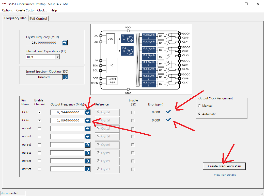
Nous aimerions par exemple un softrock lite II sur 0,136 Mhz et un autre sur 0,474200 Mhz.
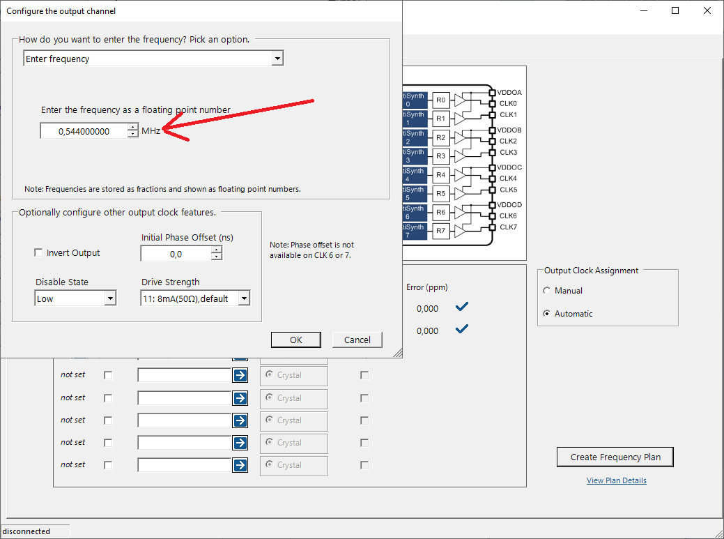
Pour un softrock il faut multiplier par 4 car il y a un diviseur, soit 0,544Mhz et Mhz.
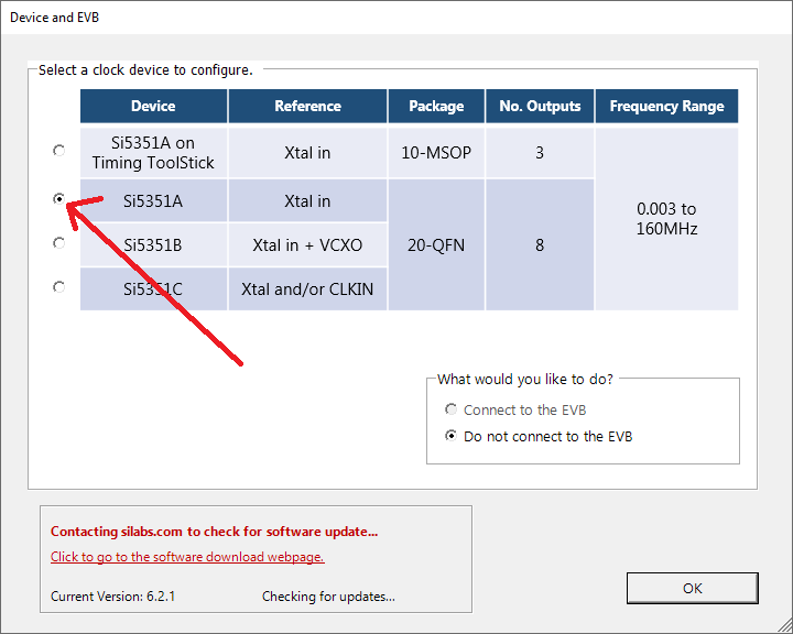
Il faut exécuter le logiciel et générer les registres comme ce:
a.Sélectionner le SI5351A dans la liste.
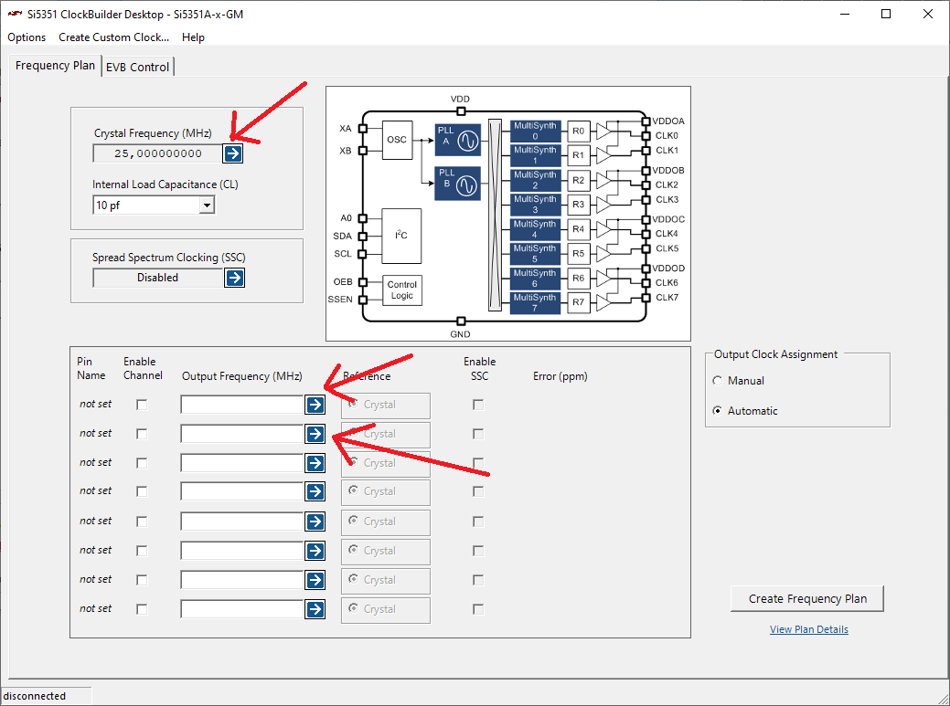
b.Sélectionner la fréquence de votre quartz, tcxo ou ocxo. Cliquer ensuite sur l’une des trois premières flèche de configuration pour les sorties.
c.Insérer la frequence souhaitée et adapter au besoin le Drive Strength qui est la puissance maximal de sortie programmable.
d.Cliquer sur « Create a Frequency Plan » pour valider les paramètres et créer les registres.
e.Exporter les registres avec Options>Save device registers (not for factory programming).
Vous pouvez ouvrir votre fichier, voici un exemple:
|
1 2 3 4 5 6 7 8 9 10 11 12 13 14 15 16 17 18 19 20 21 22 23 24 25 26 27 28 29 30 31 32 33 34 35 36 37 38 39 40 41 42 43 44 45 46 47 48 49 50 51 52 53 54 55 56 57 58 59 60 61 62 63 64 65 66 67 68 69 70 71 72 73 74 75 76 77 78 79 80 81 82 83 84 85 86 87 88 89 90 91 92 93 94 95 96 97 98 99 100 101 102 103 104 105 106 107 108 109 110 111 112 113 114 115 116 117 118 119 120 121 122 123 124 125 126 127 128 129 130 131 132 133 134 135 136 137 138 139 140 141 142 143 144 145 146 147 148 149 150 151 152 153 154 155 156 157 158 159 160 161 162 163 164 165 166 167 168 169 170 171 172 173 174 175 176 177 178 179 180 181 182 183 184 185 186 187 188 189 190 191 192 193 194 195 196 197 198 199 200 201 202 203 204 205 206 207 208 209 210 211 212 213 214 215 216 217 218 219 220 221 222 223 224 225 226 227 228 229 230 231 232 233 234 235 236 237 238 239 240 241 242 243 244 245 246 247 248 249 250 251 252 253 254 255 256 257 258 259 260 261 262 263 264 265 266 267 268 269 270 271 272 273 274 275 276 277 278 279 280 281 282 283 284 285 286 287 288 289 290 291 292 293 294 295 296 297 298 |
#Do not modify the contents of this file. #BEGIN_PROFILE #Date = Saturday, February 15, 2020 8:38:53 PM #Software version = 6.2.1 - May 13, 2014 #File version = 3 #Part number = Si5351A-x-GM #XTAL (MHz) = 25.000000000 #Mode = Automatic #PLL A # Input Frequency (MHz) = 25.000000000 # F divider = 1 # PFD (MHz) = 25.000000000 # VCO Frequency (MHz) = 643.008000000 # Feedback Divider = 25 2251/3125 # Internal Load Cap (pf) = 10 # SSC disabled #PLL B # Input Frequency (MHz) = 25.000000000 # F divider = 1 # PFD (MHz) = 25.000000000 # VCO Frequency (MHz) = 701.816000000 # Feedback Divider = 28 227/3125 # Pull Range (±ppm) = 0.0 #Output Clocks #Channel 0 # Output Frequency (MHz) = 1.896800000 # Multisynth Output Frequency (MHz) = 1.896800000 # Multisynth Divider = 370 # R Divider = 1 # PLL source = PLLB # Initial phase offset (ns) = 0.000 # Error (ppm) = 0.0000 # Powered = On # Inverted = No # Drive Strength = b11 # Disable State = Low # Clock Source = b11 #Channel 1 # Powered = Off #Channel 2 # Output Frequency (MHz) = 0.544000000 # Multisynth Output Frequency (MHz) = 0.544000000 # Multisynth Divider = 1182 # R Divider = 1 # PLL source = PLLA # Initial phase offset (ns) = 0.000 # Error (ppm) = 0.0000 # Powered = On # Inverted = No # Drive Strength = b11 # Disable State = Low # Clock Source = b11 #Channel 3 # Powered = Off #Channel 4 # Powered = Off #Channel 5 # Powered = Off #Channel 6 # Powered = Off #Channel 7 # Powered = Off # #REGISTER_MAP 0,00h 1,00h 2,18h 3,00h 4,00h 5,00h 6,00h 7,00h 8,00h 9,00h 10,00h 11,00h 12,00h 13,00h 14,00h 15,00h 16,6Fh 17,80h 18,4Fh 19,80h 20,80h 21,80h 22,80h 23,80h 24,00h 25,00h 26,0Ch 27,35h 28,00h 29,0Ah 30,DCh 31,00h 32,02h 33,74h 34,0Ch 35,35h 36,00h 37,0Ch 38,09h 39,00h 40,03h 41,A3h 42,00h 43,01h 44,00h 45,B7h 46,00h 47,00h 48,00h 49,00h 50,00h 51,00h 52,00h 53,00h 54,00h 55,00h 56,00h 57,00h 58,00h 59,01h 60,02h 61,4Dh 62,00h 63,00h 64,00h 65,00h 66,00h 67,00h 68,00h 69,00h 70,00h 71,00h 72,00h 73,00h 74,00h 75,00h 76,00h 77,00h 78,00h 79,00h 80,00h 81,00h 82,00h 83,00h 84,00h 85,00h 86,00h 87,00h 88,00h 89,00h 90,00h 91,00h 92,00h 93,00h 94,00h 95,00h 96,00h 97,00h 98,00h 99,00h 100,00h 101,00h 102,00h 103,00h 104,00h 105,00h 106,00h 107,00h 108,00h 109,00h 110,00h 111,00h 112,00h 113,00h 114,00h 115,00h 116,00h 117,00h 118,00h 119,00h 120,00h 121,00h 122,00h 123,00h 124,00h 125,00h 126,00h 127,00h 128,00h 129,00h 130,00h 131,00h 132,00h 133,00h 134,00h 135,00h 136,00h 137,00h 138,00h 139,00h 140,00h 141,00h 142,00h 143,00h 144,00h 145,00h 146,00h 147,00h 148,00h 149,00h 150,00h 151,00h 152,00h 153,00h 154,00h 155,00h 156,00h 157,00h 158,00h 159,00h 160,00h 161,00h 162,00h 163,00h 164,00h 165,00h 166,00h 167,00h 168,00h 169,00h 170,00h 171,00h 172,00h 173,00h 174,00h 175,00h 176,00h 177,00h 178,00h 179,00h 180,00h 181,30h 182,00h 183,D2h 184,60h 185,60h 186,00h 187,C0h 188,00h 189,00h 190,00h 191,00h 192,00h 193,00h 194,00h 195,00h 196,00h 197,00h 198,00h 199,00h 200,00h 201,00h 202,00h 203,00h 204,00h 205,00h 206,00h 207,00h 208,00h 209,00h 210,00h 211,00h 212,00h 213,00h 214,00h 215,00h 216,00h 217,00h 218,00h 219,00h 220,00h 221,0Dh 222,00h 223,00h 224,00h 225,00h 226,00h 227,00h 228,00h 229,00h 230,00h 231,00h 232,00h #END_PROFILE |
Vous voyez les registrer à après #REGISTER_MAP et vous pouvez les adapter dans le tableau SI5351_Reg_Store_init.
Je vous laisse le soin de trouver un tutorial vous expliquant comment configurer un IDE Arduino pour envoyer sur un Attiny85.


